Where the conveyor can be made to conform to these practices, the user who prefers to make his own layout can readily do so, using the practices outlined in the following step by step guide.
The following specifications should be sketched or listed on the layout drawings:
The Carrier is usually connected to the overhead conveyor by a bolt thru a clevis “H” attachment. This allows the carrier to hang pendantly or vertically on inclines and declines. A carrier connected to two clevis attachments will follow the path of chain or inclines and declines, and part must be held in place to prevent them from sliding to the low point of the carrier on inclines and declines. Other types of attachments are available.
Conveyor with carriers that are loaded from one side
only must have proper directions of travel at “Unload”
point.
After the carrier has been designed and trolley
attachments selected, establish the overall carrier
dimensions, including parts being conveyed. Make compact
as possible.
Elevation of rail at conveyor “Load” and “Unload” points is determined by the type of carrier hook, and the connivance of handling the part. Sometimes elevation of rail is determined by headroom under chain, required when operators must pass under conveyor.
Rail elevation should be shown from floor to top of I-beam track.
The height of rail between “Load” and “Unload” points depends on such factors as ceiling heights, truss height, clearance height under part being carried, obstructions, aisles, etc. Guards from conveyors add to clearance requirements.
The size of the conveyor system required is determined by
two factors, total chain pull, and the load to be carried
on each trolley.
Plants with a large amount of overhead conveyors often use
No. 458 systems instead of No. 348 for even the lightest
loads, in order to standardize maintenance parts and
permit future extension or combination of individual
conveyors. The installed cost of No. 348 conveyor is not a
great deal less than No. 458.
To calculate approximate chain pull, assume that the chain and trolley assembly weighs 10 lbs. per foot. Exact weights will be found in Table 3 when conveyor size and trolley spacing are known.
Measure the length of the conveyor on the layout and calculate approximate total weight of chain and trolleys. Add to this figure the total weight of empty and loaded carriers to determine total moving load. Multiply total moving load by factor indicated in Table 2 to find approximate chain pull. Choose a suitable chain from Table 4. Estimate the weight of a loaded carrier and consult Table 5 to make certain that the trolley corresponding to the chain size will not be overloaded.
In some cases, calculated chain pull for a conveyor may exceed the allowable for a particular chain even though the trolley loads may be well within the capacity of rail and trolleys. Practice in such cases is to use two or more synchronized drive units. A more detailed discussion of this problem can be found in the Drive Unit Section of the Anchor Online Product Catalog.
Sometimes it may be found that unit load exceeds the single trolley capacity for a selected conveyor size even though the calculated chain pull is within the allowable limits.
This problem has two possible solutions:
In the case of 4-inch conveyors a third alternative is available.
A 6-inch trolley and rail utilizing a No. 458 chain, can sometimes prove a more satisfactory solution than the selection of either the 4-inch multiple trolley and load bar arrangement or the 6-inch trolley with No. 678 chain.
Recommended minimum vertical curve radii are shown in Table 6. Shorter radii may be used in unusual cases if chain pull is light and carrier clearance permits.
Make two “Elevation” templates or carrier and part, and move properly spaced templates over scaled drawing of path of vertical curve. Check that carriers and parts clear each other and also clear the chain. (Note that carrier spacing must be a multiple of twice the chain pitch.) Determine tentative trolley spacing.
Selection of a standard radius for all horizontal turns simplifies installation, reduces parts inventory, facilitates future conveyor rearrangements and makes all turn components interchangeable.
Avoid extremely short radius turns. Table 7 gives recommended minimum radii for chosen conveyor chains.
A length of straight rail must always be provided between the tangent point of a horizontal turn and the tangent point of a vertical curve. On conveyors with the load suspended from one two-wheel trolley, this length should not be less than the longest trolley space. On conveyors with load suspended from two points, the length of straight rail should not be less than the distance between these two points.
Make two “Plan” templates of carrier and part, move properly spaced templates over scale drawing of path of horizontal turn. See that carriers clear each other.
Use these templates layouts to determine clearance for guards.
The clearances required between parts of carriers will often determine the minimum horizontal turn radius, minimum radius of vertical curves, and the angle of incline and decline of sloping tracks
Conveyor speed in feet per minute is calculated from the required number of parts per hour multiplied by the carrier spacing in feet, divided by (60) times the number of parts per carrier.
Conveyor Speed FPM = Parts per Hour x Carrier spacing in Feet / 60 x Parts per Carrier
In order to allow for variation in production requirements, it is desirable to set a maximum speed greater than that calculated and use a variable speed drive. A speed of 50 to 70 feet per minute is usually considered a conservative maximum. Thirty feet per minute is more convenient for loading and unloading and reduces wear on chain and trolleys.
Chain pull is the result of fraction on the trolleys caused by moving load, vertical dips and rises, and friction in chain flexing around horizontal turns. Also influencing chain pull is lubrication, temperature, and foreign matter collecting on the track.
If parts are to be carried up an incline another figure must be added to the friction chain pull for the lift load. This lift load is calculated by multiplying the total vertical rise in feet by the “live load” per foot of conveyor.
Total chain pull equal the pull due to the friction of the total moving load, plus the lift load.
For extremely long conveyors and conveyors with a complicated chain path, or where more than one drive is required, it is necessary to make an accumulated chain pull computation.
When the maximum speed and total chain pull have be
determined, the horsepower required can be calculated by the
following formula:
Horsepower= Total Chain Pull in lbs. x max. speed in f.p.m.
/ 33000 x efficiency
Allowance must be made for losses in V-belt drives, variable speed transmission, chain drives, etc. An efficiency figure of 70% will be correct for most drive units.
A drive should be located at the highest point of conveyor immediately preceding a decline, if possible. Good practice dictates that the drive be located to apply a pulling force ahead of the greatest load.
Drive units can be either sprocket or caterpillar type and constant or variable speed.
Refer to Drive Unit Section and determine the style preferred and size required. Select a specific drive and locate it on the layout drawing.
It is recommended that a take-up be used on most overhead trolley conveyors.
It is always desirable to locate the take-up as soon as possible after the chain leaves the drive unit. (A vertical curve following the drive will also help to remove slack chain).
When a trolley passes over the upper bend of a vertical curve, it imparts to the rail and trolley a force greater than the load being carried. Chain pull, trolley spacing and vertical curve radius are factors influencing the magnitude of this force.
Table 8 presents data to be applied to determine the thrust load. Layout and design alterations may be necessary to insure that trolley reactions on the rail are not excessive. Table 9 indicates maximum recommended radial load per two-wheel trolley.
Refer to the section on Guards & Housings and select necessary guards. Indicate these on the drawing.
Drip pans are often used under traction wheel turns and drive units to prevent oil from dripping onto parts, workers, floors, etc.
Safety devices used on conveyor inclines and declines to prevent loads from backing up or running forward if the chain breaks or becomes disconnected from the drive are described in the Vertical Curve Section.
Expansion joints should be provided in conveyor track in ovens, degreasers, washers, etc. where temperatures vary considerably, and at building expansion joints.
Spacing of expansion joints is determined by maximum temperature variate and must be computed for each installation.
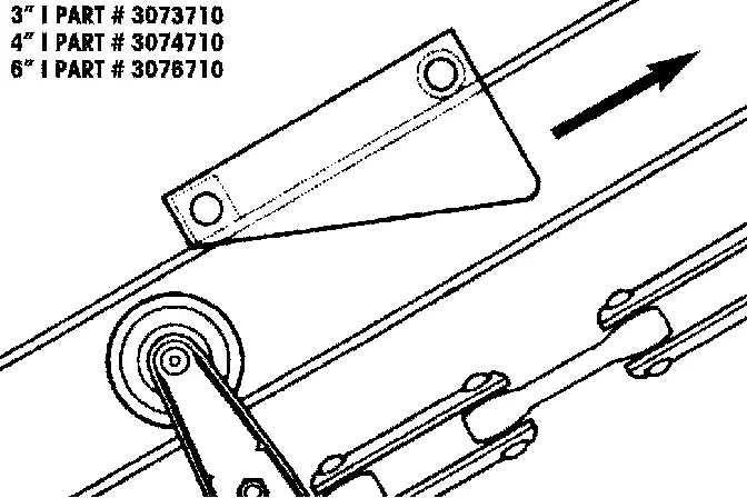
Figure 1
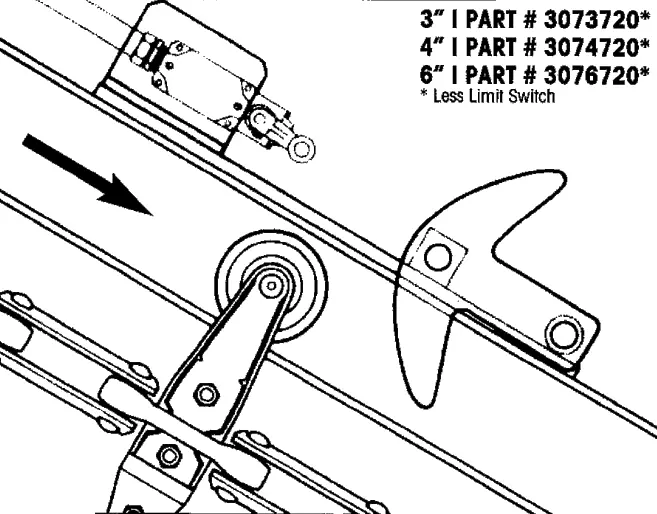
Figure 2
Changes in elevation of overhead conveyors are easily accomplished with vertical curves in the conveyor track. Anchor vertical curves are fabricated from high carbon steel rail and particular care is exercised to form smooth uniform bends without deforming the rail. They are usually shipped as single bends of a given radius and degree. Two single bends are assembled on the job to form a complete compound vertical curve, usually a piece of straight rail is inserted between the bends to gain required elevation.
Large radius curves and gradual inclines, where space permits, will reduce wear on chain, trolley, and rail. Clearance between trolleys and track flange should be checked as discussed in the section of Application Engineering.
If the change in elevation of a vertical curve is 5′ 0″ or more, incline or decline safety devices are recommended to prevent conveyor runway in the event of chain breakage. Incline safety devices (Fig.1) are lifted by the trolley side arm to allow conveyor to operate up incline. However, they act as a positive stop to prevent down hill travel.
Decline safety devices (Fig. 2) are held in the up position by a
latch mechanism during normal conveyor operation. A sudden
increase in the speed of the trolley passing under the release arm
will trip the latch and drop the stop in front of the next
trolley. The stop operate a limit switch to stop conveyor
drive.
Incline safety device can also be furnished with limit switches to
stop the conveyor drive if the chain breaks.
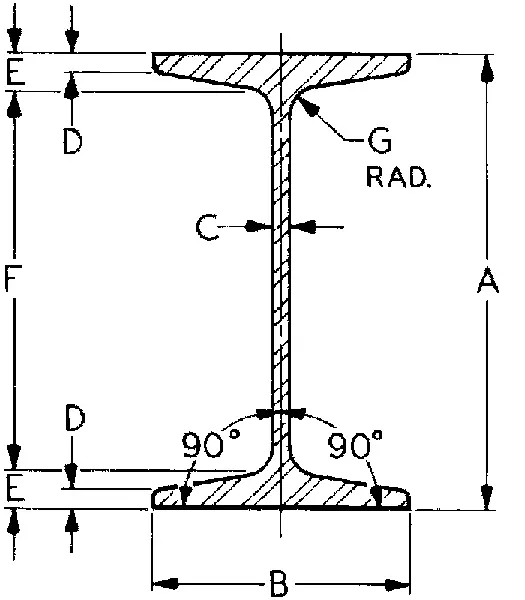
The overhead conveyor track is specially rolled I-beam section produced from C-1045 steel to the following specifications:
The specially rolled I-beam conveyor track is available in 3-inch, 4-inch, and 6-inch track size. The conveyor track is stocked in 20 ft. lengths and can be cut to any required length.
Due to high carbon content, our conveyor track assures longer wear life and better resistance against track flange peening than standard structural I-beam sections. Also, to assure a uniform cross section of the track, the track is rolled under controlled conditions. Standard mill tolerances, often the cause of misaligned joints and out of square and out of parallel conditions are eliminated.
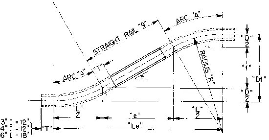
Solution of Combined Vertical Curve Problems
Note: Single bent rails are fabricated with a straight tangent section “T” on each end.
Formulae